Tuesday, May 25, 2010

Perimeter Bearing Haunch

Whenever a new building system is encountered by designers and engineers, the most frequent question is, "How do we do this?" followed by, "Then, how do we do that?" This project was no exception, the biggest question being about how to integrate hollow core planks for a trim floor system depth with only 8"or 6" of concrete thickness on which to bear the planks on the ICF perimeter wall. That was a mouthful...but the answer is not. Just like the foam was easily manipulated to provide for integrated brick ledges and pilasters (in previous posts), the forms shown here have been altered to allow for two and a half more inches of concrete bearing surface.

About 18" of the inside panel on the top course of forms was removed. This process involves placing the last course without glue, numbering them in sequence, establishing the height of the necessary cut at each corner of the building, then chalking lines on the walls between those marks. The forms are then brought back down and cut along those lines, then glued and returned to their numbered position on the wall.

A portion of each metal tie is left on the form so that concrete will hold fast to it.

This wider angle shot helps establish the perspective for the next photo. Here you can see how plywood has been fastened to the inside surface of the forms reaching up beyond the edge of the foam to allow for the concrete to come out to the surface of the foam.

A good string line makes a good straight wall. This string line will be used to make final adjustments to straighten the wall right up to the last drop of concrete on pour day.


A little closer and different angle photo here shows the intense schedule of rebar stirrups prescribed for the bearing conditions of the coming hollow core planks.

The formwork includes the integration of laser-leveled OSB strips to ensure that the height of the entire perimeter of the wall is consistent and uniform.

A smooth enough surface for the hollow core planks is screeded at the end of pour day. If you look closely, you can see that the bracing (the vertical aluminum pieces) is used to form the concrete as well, so that they did not have to be furred out to account for the thickness of the OSB forms.


Pour day, interestingly enough, is one of more uneventful days of an ICF install...if everything has been executed well. That was certainly the case here. Duties are assigned to the workers in order of priority so that if a louder voice calls, a quick shift to the needed spot is made and the pour can continue smoothly. A hundred and twenty-four yards of concrete were poured in six hours, and after tweaking, straightening and screeding, the crew got the rest of the afternoon off...while the concrete carried on the work as it cured.

If you can't see the care and attention that was given to this assembly, you're not paying attention. The precision execution from footing to float (screeding at the top of the wall) is evident in the uniform consolidation of the concrete, the straight walls, and accurate placement of rebar. There is a night and day difference between a crew who is familiar with ICFs, and one that is learning.

Bracing and formwork is removed to allow work to continue the day after the pour.


I am curious to hear the assessment of the haunch by the hollow core installation crew, because it sure seems like it will be smooth sailing from where I stand.

Integrated Pilasters

Sometimes folks new to ICFs are really confused when they see foam forms. They know the foam can't be the structure of the wall, but are sometimes embarrassed to ask. Once they hear what the space in the middle of the forms is for, or they see a finished assembly with the concrete inside, it all makes sense. One of the biggest lessons in ICF education is the realization that not only are the forms simply that, forms for concrete, but the reinforced, cast-in-place assembly is structurally second to none, and that a properly engineered and quality-controlled ICF product is plenty strong to handle the demands of placing concrete. Any compromise (a.k.a. blowout) of the forms is more likely to take place where a form has been cut, or near an opening, rather than in a running section of wall, and these happen less and less frequently as the industry and the products mature. In other words, installers are aware of the weaknesses, and account for them with additional shoring where appropriate.

A simple detail afforded by the flexible nature of ICF forms is the integrated pilaster. While the thickness of the concrete inside the forms in the assembly shown here is 8", 2.5" of foam on either side provides potential increased thickness of the concrete structure which, with additional reinforcement, can provide a stronger structural member (a pilaster) without needing to bring the concrete proud (beyond the plane) of the surfaces of the forms.

OSB forming, bolstered by lumber and steel tie wire, makes integrating pilasters a simple process.

It can take a little bit to orient yourself to the perspective of this photo. You are looking down the surface of the wall to show how foam was removed and the wood form is placed on the outside plane of the form. This, additionally, provides a much easier way to install the rebar cage specified.


This is an even wider pilaster.
Here, you can see each of these pilasters with the concrete set and forms removed. Placed in the the pockets at the top of each pilaster are embed plates, onto which steel beams will be placed.

In this photo, again, looking down the surface of the wall, you can see the corner of the steel embed plate, onto which a steel beam will be welded for an element of the structure that extends beyond the wall surface. This plate was placed in the wet concrete on pour day. Notice how the concrete and surface of the forms are in the same plane.


Once sheetrock is placed on the forms, no one will realize that this pilaster is present, providing a cleaner, uninterrupted surface likely not otherwise possible with a different wall assembly.

Friday, May 21, 2010

Integrated Brick Ledge a simple step with ICFs

Once again, we're dealing with EPS, expanded polystyrene, easily manipulated with simple tools like the handsaw or a key hole saw. This makes the system flexible in its structural capacity, since we can shape forms and add reinforcement for liquid concrete to conform to our designs. Read further for a walkthrough of the brick ledge process.

Holes are simply carved between the steel ties with a hand saw. The steel ties remain intact for form strength while allowing a place for reinforcement and concrete to reach out of the formwork.


These are specially bent rebar called stirrups, prescribed by the project engineer, which are fastened to the 12" on center vertical rebar. They connect the ledge, on which two and a half stories of brick will rest, to the 8" concrete wall inside the forms making a monolithic structure.


During concrete placement the, in this case, second lift was stopped at the height of the ledge to allow consolidation (here mildly assisted by a concrete vibrator) without spilling concrete. You can see how clean the form work is, a testimony to the care required, and employed, by the pump operator and hose man.

Since we're not dealing with a finish surface, the extent of the detailing is what you see here.


Removal of the formwork...


Reveals a clean, effective ledge which will eliminate the need for many hundreds of square feet of masonry which would otherwise be need to run all the way down to the footings.

Form work is easily provide around corners, and at various heights.

Friday, May 14, 2010

North Wing Progress

One of the challenges with any project of this size is coordinating each trade so that prerequisite work is completed in a timely fashion to make sure the project can progress smoothly. You can see in these progress shots that while the ICF phase is under way, digging for more footings and plumbing is also taking place, even on pour day! It will really start to get interesting once the hollow core planks come on site for the floor systems. Coordinating their installation, with the masons for the interior walls (and there are a lot...this is a residence hall after all!), ICF for exterior walls, plumbing, and electrical, among others, will be a fascinating exercise.


Bracing ICF Walls

One of the most frequent comments I've received while walking this site with folks new to ICFs is, "That bracing system is slick!", or something to that effect. Indeed it is. The fraction of its weight and complexity compared to traditional forms and bracing, and the lesser amount of space to store and transport these materials is no small thing when comparing cast-in-place concrete systems. I've mentioned it before, but it deserves some more attention, that the form work being (or becoming) the insulation for the wall means we have a system instead of an individual component, several critical features built into one step. Concise and complete ICF bracing systems facilitate the simplicity of the assembly process.
The brand used here is called ReechCraft, and consists of 4 components. Above are, from the top, walk board attachments, diagonals/turnbuckles, and hand rail attachments.

Here, the lightweight aluminum "strong-backs" are stacked.

A "strong-back" with a 4 ft. extension for the taller wall application pictured in some following photos.

The bracing system during assembly. Walk boards and hand rails are not yet installed.

The 4' extensions enable taller wall applications, such as this 15' plus section here, the sunken area for the chiller room, where larger mechanical equipment will be located.

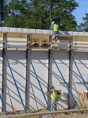
The integrated walk board provides a safe, OSHA-approved scaffolding in addition to its bracing and straightening capabilities.

Here, this worker is measuring the space between the string line, which is to be an established distance from the wall surface, and the wall, (in this case inside the bracing, for consistency, as there is plywood forming in between). He relays the information to the worker on the ground...

...who turns the turnbuckle clockwise to bring the wall closer, or counterclockwise to push the wall out. These finer adjustments are often made while the wet concrete is in the wall. The force of concrete placement can often negate incremental adjustments on such a fine scale (1/8" to 1/16"), so tweaking precisely prior to the pour is lost time.

Wednesday, May 12, 2010

Stacking ARXX Steel Blocks

Legos® get lots of air time when describing the simplicity of stacking ICF forms. With ARXX Steel forms, the interlock between adjacent blocks is provided by tongues and grooves. All ICF forms require some method of holding forms together, clips or snaps or the like. In ARXX Steel's case, foam glue is used in the grooves (bottom of the form) of a loose form before fastening it to the wall assembly. This foam glue is extremely strong so that after just a few minutes, you will not be able to separate the forms without physically cutting them apart. This provides strength and resilience during the concrete pour. Maybe an even more important benefit is that the combination of glue with the tongue and groove feature provides resistance to deflection, or settling of the forms during concrete placement. ARXX Steel forms retain their assembled height, and on a building with critical dimensions (what building isn't?) this is key. A ten foot floor to floor height is sacred, no room for squashing the forms to 9' 11 1/2".

Glue applied in each groove (about a 1/4 to 3/8" bead)...

A two man team can really speed up the process. While one is placing the form in the wall, the other glues the next block which is ready when the first block is set.

These blocks were going in at a rate of about 1 every 30 seconds. Granted, with an intense reinforcement schedule and unique form cutting such as utilized on this project, stretches of speedy stacking are frequently interrupted to allow for prescribed rebar placement. With a 10-person crew, this full wall assembly is installing (from footer to concrete pour--stacking, rebar, bracing, buck assembly and placement, concrete placement) at a rate of about 80 forms per day, or 8 forms per person per day. The kicker is that these walls do not require the additional man-hours to insulate, fur out, or wrap the wall assembly. It is a complete, finish ready system.

Another interesting fact about this ICF building -- It will have about 50,000 square feet of ICF wall. But, because of the cast-in-place nature of the assembly, the building will consist of only 30-35 single panels of monolithic concrete. So the average size of each unique structural section is about 1500 square feet!

Tuesday, May 11, 2010

Preparing the footing

A little rain and a week or two can clutter a perfectly good footer.

A little housekeeping...

...and they're ready for chalk lines.

"Pocket" laser levels are handy tools. It's hard to see, but the orange string near the top of the picture is a section line sighted by the builder, used to establish critical dimensions of the building. The laser level helps transfer this section line down to the surface of the footing with ease.

Then, it's just a matter of marking dimensions of the forms...

...and snapping chalk lines.